

The additional options for creating a symbol listed are not used for this example, but you can use them when creating your own symbol. If you place the component on an existing wire, the wire breaks.

AutoCAD Electrical toolset provides a default name for the new symbol based on the attribute template selected. Enter the Name and file path or keep the default.dwg file, while Block creates the symbol for this drawing file only. Click Base Point: Pick point and select the center of the rectangle.HDV1_BTL_1-.dwg - “corner” connection for dual horizontal circuit.VDV1_BTT_1-.dwg - “tee” connection for dual vertical circuit.HDV1_BTT_1-.dwg - “tee” connection for dual horizontal circuit.VDV1_BT_1-.dwg - with “dot” for vertical one-line circuit.HDV1_BT_1-.dwg - with “dot” for horizontal one-line circuit.

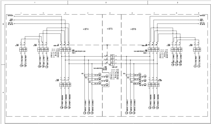
The following bus-tap symbols are supplied: These bus-tap symbols allow various reports to report accurately on a one-line circuit, whether a single circuit or a dual circuit representation. There is another version of the symbol on each of the two circuit "legs", each marking the point where that part of the dual circuit starts. One at the normal point where the circuit ties into the bus. On a dual circuit one-line template, there are three bus-tap symbols. Break into the one-line bus where the circuit connects.Provide an anchor point for the one-line circuit representation that begins at this location.The bus-tap symbol can have two functions:


 0 kommentar(er)
